
Changes and variations


Right: Not a great photo. If you look closely on an inner cap where the red circles are you will (some times) find a number. This number relates to the number cavity it came out of in the mould tool. Mould tools tended to be 18, 24, 32, 48 impression. They were mounted on injection moulding machines and fed with granulated plastic. An Archimedes screw thread screwed the molten plastic into the mould where it set. It would then open and ejector pins would eject the part, then the scrap sprue. They would take any where between 40 seconds to over a minute to perform a cycle. Most plastic parts had cavity numbers moulded in them. This way if there was a problem with a part it could be related back to the cavity and have it blocked off rather than taking the entire tool out for repair.
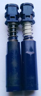

Left: A clearer photo showing the cavity number on BP mechanisms.

The Flighter Parker "25" was offered with the nib sizes of Extra Fine, Fine, Medium and Broad.
Date codes were introduced in 1980.


Right: Slightly odd / rare to find this marking. I would assume a Toolmaker has engraved this component No.16. They may of been working on the mould tool and marked this component up as 16 to denote the cavity it came from. This would also mean the tool was capable of moulding 16 parts every cycle.


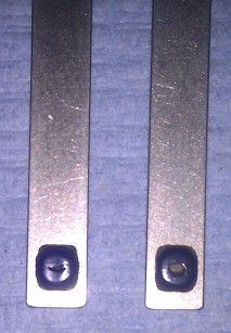
Left: Shows the variation in symbol prints on a blue trim clip. The smaller, thinner, crisper print on the left tends to be on earlier pens. The bolder on later pens and can some times be untidy and not as crisp.
Right: On the rear of the clip are tooling marks. Some had a horizontal line, others had a hole. This was probably to ensure orientation when the plastic was melted in position.
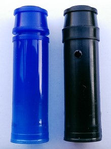
Right: All three shells / front ends; FP, FT, RB. Although there is also a hybrid type which accepts FT and RB refills.
An important feature to note is the groove around the chrome point. This clicks into place within the inner cap. If the plastic inner cap is worn you may encounter a loose cap. To resolve this you'll need a new inner cap, or it might be saved by stripping apart and making a non official adjustment.
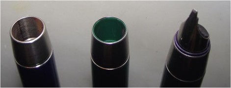
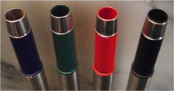
Left: Another subtle difference to note is the plastic section / front end on the FP, where the feed pushes into.
From left to right;
1.Blue metal lined section. More than likely found on early Mk1's.
2.Green recessed plastic liner.
3.Orange flush or level plastic liner.
4.Black protruding plastic liner.
Left: Transition from metal, to recessed, to protruding plastic section.
Courtsey of Shaughn FPN

Over the years of manufacturing the Parker 25 there were very few changes unlike some other Parker models. Although there were subtle changes that become more obvious when comparing parts side by side.
MK0, MkI, MkII, MkIII and MkIV
MK0 - Very early FP's (in the first few months I would guess) had a metal liner on the front end. There was no plastic inside. The nib and feed were pressed in. These are incredably rare and nibs tend to corrode in against the steel. They were only on very early FP shells, then they were produced with plastic lining. I have only seen them in blue. See right.
MkI - FP had a breather hole in the nib, a 'flat top' inner cap with large breather hole on the side and a stainless steel barrel thread insert. The stamp was the broad PARKER MADE IN ENGLAND with the logo above.
MKII - was missing the hole in the nib, but still a 'flat top', broad stamp PARKER MADE IN ENGLAND and logo above and now with brass barrel thread insert.
MKIII - had a 'dimpled / ridge' top with groove on the inner cap and no breather hole (unseen when assembled), broad PARKER MADE IN ENGLAND but now the logo was moved to the left of PARKER and a date code introduced.
MKIV - had 'ridge / dimpled' top, brass thread, stamped with smaller narrower PARKER MADE IN UK and logo to the left of PARKER and date code.
The Parker 25 shared a couple of generic parts and sub assemblies that were used on all of the five models; the cap and clip. Otherwise the FP, RB and FT shared several parts and the BP and MP shared some other parts such as the barrel and ratchet assembly. But overall the pen had very few parts, an aim set out in its original design brief.
FP had 10 components
RB had 9
FT had 9
BP had 11
MP had 10
Right: Early 1975 MK1 FP nib had a hole in. This was no longer present a year later.
Below: Very early pens had a stainless steel thread insert in the barrel. This was soon replaced with brass. From left to right: Stainless steel, possibly brass and brass.
The 'flat top' ended and was replaced by the 'ridge top'.
Left: Breather holes in early FP inner caps were larger than later ones. On the left is a damaged inner cap with large breather hole. The right is a later version.
Below: BP / MP rachet assembley components varied in colour materials. Left, an early black assembly compared to a later blue.
Below right: two blue assemblies; unseen parts varied in colour; black and white.
Below left : Later versions of the FT and RB inner cap had a groove around the top diameter, on left. This may of been to reduce friction and aid assembly. Earlier versions had a straight / flat edge, on right, with no groove.
Below Right: Same difference with FP inner caps, A groove present on later versions on left and no groove on earlier ones, right.
Early MP had a much larger lead size compared to later models.
The printed logo on the clip varied possibly from batch to batch. Some were thin crisp lined logos, others were heavier solid logos.
Righ and leftt: BP cone piece in front of barrel retaining spring, varies in colour and size; pink, black, white and green. Maybe moulded from left over plastic granules. Oddly the BP works without this part.
Date codes change. Click here
Below: PARKER stamp changes from early broad wide stamp to narrower thinner stamp.
Below: Stamped Parker logo moves from above PARKER stamp, to beside on the left. Stamp changes from MADE IN ENGLAND to MADE IN UK.